
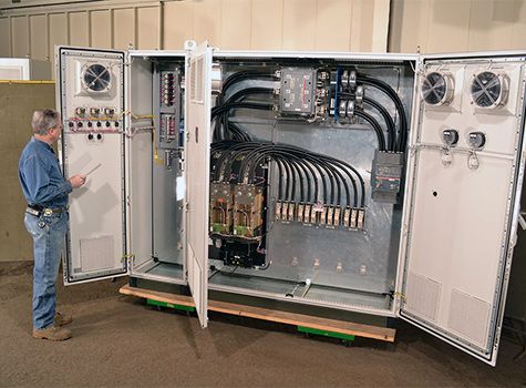
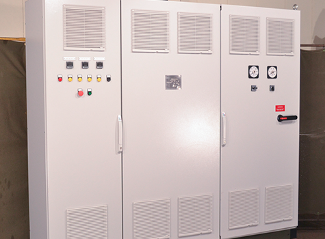
A control panel is used to provide electrical power, controls, and sensor connections to electrical equipment to allow the end user precise monitoring and control of their electrical process heaters. ACG designs and fabricates customized control panels in house to accompany our electrical heating process equipment such as electric immersion heaters, impedance heaters, and radiant furnaces. We can sell them both as an accompanying piece of equipment to an electric heater order or as a custom stand alone item. Historically we have not advertised control panels as a stand alone offering, but we are well positioned to design and fabricate them to a customer's requirements even if we have not fabricated the associated process equipment.
ACG can manufacture control panels in both the Coatesville and Beith locations with CSA or ATEX certifications as required by the end user's local jurisdictions. Some components within the panels will differ based on the fabrication location and availability of subcomponents.
Panel Sizes: Depth is roughly limited to 24" and Height about 86". Width is technically unlimited with modular designs where multiple sections can be added side by side, but manufacturing and shipping become problematic for items larger than a 3 door design or about 117.5".
Material of Construction: The material of construction will depend on the NEMA type enclosure rating that the customer requires. Type 12 is Carbon Steel with powder coating for use in an indoor non-corrosive environment. Type 4x is for outdoor use in a corrosive environment and typically made of Stainless Steel 304 or occasionally Stainless Steel 316 when requested by a customer.
Area Rating: Armstong holds a CSA certification for non-hazardous areas only, and we self-certify for hazardous locations. To provide control panels for a hazardous location, we self-certify to Cl 1, Div 1/2, Group A-D with a type Z purge with a 4X enclosure. We do the same thing for ATEX equivalent. CSA certification is used in the US & Canada, and ATEX is used in Europe and abroad. A non-hazardous location is one where explosive atmospheres (gases, vapors, or dust) are not expected to be present, while a hazardous location is one where explosive atmospheres are expected to be present, and the equipment must be designed to meet safety requirements for fire or explosion risk.
Indoor vs. Outdoor Installation: Indoor is non-hazardous typically designed at 30 degree C unless otherwise specified by customer. Outdoor is designed at 40 degree C unless otherwise specified. Area classification is determined by customer specification based on the local conditions and where the panel will be installed. Some customers locate the panels in a control room away from the process area where multiple pieces of equipment can be monitored at once, while others locate the panel right next to the equipment in the process area for direct hands on monitoring and control. The different installation locations drive the requirements for the panel enclosure design and materials of construction.
UL Certification: ACG can certify to UL 508A under our CSA / CSAus certificate for non-hazardous areas. We self-certify for hazardous areas, but those panels do not carry a UL certification.
Control: ACG can design a panel with Control Relays or a PLC. Both can be CSA certified. PLCs tend to be more expensive in components and design time.
Some Required information would be: power duty requirement of the equipment to be controlled (heater kW rating), cable entry location (top or bottom of panel), area classification (if any), SCCR rating (typically can't be higher than 100 kA and this also raises the cost of the main circuit breaker), customer required IO (especially in PLC applications) (ACG typically provides basic IO of one DI ON/OFF and SCR command AI signal).
We can customize panels as required by customers, but more complex and bespoke items become more expensive.
A standard Armstrong panel should be an SCR resistance heater control panel built for non-hazardous location in a control panel room with a type 12 enclosure. Included IO being a Digital ON/OFF signal and an Analog control signal to the SCR. Our minimum SCCR should be 65 kA to meet what tends to be the industry standard.
Cost adders would be type 4 and 4x enclosures, area classification, and more IOs than listed above. PLC would also be a cost adder.
ACG offers field service for equipment installation & troubleshooting either as a cost adder or included in the price of the panel as a value added part of sourcing an Armstrong panel.
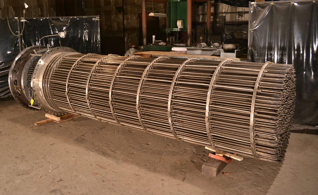
An electric immersion heater shares many visual similarities with a shell and tube type heat exchanger and appears to be a u-tube type bundle inserted into a shell, however, there is no tube side fluid present in the bundle. Instead, the bundle consists of electric heating elements arranged in a u-bundle configuration attached to a flanged support plate which bolts to a heater shell. The removable bundle is electrically energized to create heat through electric resistance in the heating elements, and the process fluid flows through the shell side of the heater directly contacting the immersed heating elements, causing the fluid to heat up.
Electric heating offers advantages in heating efficiency as high power factors convert nearly all electrical energy into heat, precise heating via a uniform heat flux that can be easily controlled to meet process needs, decarbonization efforts as electric heating does not produce direct emissions and can reduce the overall environmental impact of heating equipment, it lowers hazard potential as the absence of combustion significantly reduces safety hazards to ensure a safer working environment, low maintenance costs as the electric heating elements experience less wear due to the lack of combustion ensuring less down time, and a smaller footprint requirement as electric heaters do not require fuel storage or complex exhaust systems.
EHT's are typically used in power duty ranges of 10 kW to 1 MW per bundle, with the option to include up to four bundles in a single heater shell, and supply voltages up to 600 VAC. They are well suited for single phase flow to heat a number of process fluids, and a non-exhaustive experience list of example applications is below. For higher power duties or two phase flow, an Electric Impedance Heater or a Radiant Furnace would be better suited on a cost versus footprint basis.
Example Applications:
ACG fabricates EHT's ranging in size from NPS 2.5 to NPS 42. The materials of construction vary depending on the specific process demands, but as a rule the heaters have a high design temperature to maximize the power duty in a single stage and minimize the equipment footprint and need for multiple redundant bundles. The high design temperatures limit which materials can be used in construction.
Shell materials can be Carbon Steel, Low Alloy Steel Cr-Mo, Stainless Steel 304/316/321/347, Hastelloy C276, Monel 400, Inconel 600, or Incoloy 800/H/HT.
EHT bundles are typically Stainless Stell 321, Inconel 600, or Incoloy 800/H/HT.
ACG can accommodate Design Temperatures up to 1300 °F [700 °C] and Design Pressures up to 4,000 PSIG [275 Bar]. The heater shell and bundle are both pressure containing components that are governed by ASME Section VIII Division 1 in the United States, and relevant pressure vessel codes abroad. EHT's are designed to ASME code and carry a U stamp.
While the heater bundle appears to have a tubesheet, it is designated as a Heater Support Plate and designed per ASME Section VIII Division 1 Mandatory Appendix 41, which was written specifically to address electric immersion heater design. ACG also follows UOP specifications for heater bundle design.
The heater bundle power junction box is NEMA/NEC rated for use in hazardous locations via CSA US certification in the United States and ATEX abroad. Power junction boxes are placed on the heater bundle with a standoff area between the heater support plate and the junction box to allow for ambient cooling and the use of low temperature wiring in the power junction box.
Consideration for all the following parameters goes into an electric immersion heater design:
The proprietary programs that we use for design purposes account for all the above factors as well as other considerations.
Once we have designs that meet the project requirements and our internal standards, we evaluate those options to maximize reliability within a certain price range, so we can provide the best value to the customer.
ACG's EHT's connect to customer supplied 3-Phase, low voltage supply power. ACG offers low voltage electric heaters (maximum 1,000 VAC supply power) as they provide a robust product that meets our commitment to equipment reliability.
The power output of an electric heater is defined as the Power = (Voltage\^2)/Resistance. For a 4160 VAC medium voltage heater compared to a 480 VAC low voltage heater, the medium voltage heater would require a 75 times higher resistance than for the low voltage solution to generate the same power output, which can be achieved through either increasing the resistance of the individual heating elements or increasing the number of heating elements wired in series. A higher resistance heating element is made by decreasing the diameter of the resistance wire within the element, and a finer wire is more prone to failure at typical operating temperatures due to burnout. Alternatively, increasing the number of elements wired in series significantly decreases the fault tolerance of a heater as a failure in one element would remove multiple other elements from operation, and a 4160 VAC line voltage would require seven heating elements in series to use elements of similar robustness to that of a low voltage heater.
Medium voltage electric heaters offer benefits during the installation as they do not require a step-down transformer from the operating site's medium voltage to the heater's low voltage, but the above tradeoffs introduce longevity issues that require more frequent bundle replacements resulting in increased downtime and maintenance costs. The initial savings of avoiding a step-down transformer with medium voltage heaters are then often offset by the more frequent replacement costs.
The element sheath to support plate welds are governed by ASME Sec. VIII Div 1 UW-20 and performed using an ASME Sec. IX qualified GTAW process in the same manner as a typical shell & tube exchanger weld. Welding the heating element sheaths to the support plate creates a robust leak free connection that can be validated through traditional non-destructive evaluation [NDE] methods such as dye-penetrant testing [PT] and hydrostatic testing. The welded connections contain the process fluid in the shell side where it belongs and result in a longer bundle life.
All ACG EHT heaters are 3-phase heaters. Our ability to hit certain kW ratings is limited based upon the resistance values of the Nichrome resistance wire in the heating elements. To achieve certain kW ratings the heater can either be wired as a Delta or as a Star in the terminal box. We typically wire the heater as a Delta but will sometimes wire as a Star to hit lower kW rating thresholds.
Delta are the preferred means to wire our heaters. When we design our heaters, we design them without the requirement of a system neutral. This is fine for Deltas because the risk of overvoltage is minimal in the scenario of a lost element (we still recommend rebalancing the heater if an element is lost in a Delta). In the case of a Star with no system neutral you will have a floating neutral. If you were to lose an element with a floating Star the risk of overvoltage to an element is greatly increased. Safety equipment can help mitigate this risk but a Delta in general is still preferred
ACG also prefers delta wiring over a wye/star pattern as the delta configuration does not require a neutral point between supply power phases and thus requires less wiring, hardware, and a smaller footprint to install. It allows for a more compact and cost effective junction box.
Moisture ingress into the power junction box can lead to electrical shorts of the heating elements and loss in overall rated power duty to the heater or even lead to a scrapped bundle. This can be mitigated through the inclusion of an Anti-Condensation Heater located in the power junction box to prevent moisture buildup.
ACG also designs the heating elements themselves to resist moisture intrusion through two methods: 1) Each individual element end is dipped in a sealant and baked to create a hydrophobic seal between the electrical resistance element and the power connection, and 2) an epoxy sealant is applied on the end of the elements after the hydrophobic seal is established. The epoxy provides both electrical insulation and an extra layer of protection against moisture ingress.
The process fluid in EHT's makes a single pass longitudinally along the length of the heater shell from the inlet nozzle to the outlet nozzle and directly contacts the immersed heating elements to transfer heat from the hotter elements to the cooler fluid. To achieve the maximum heat transfer for a given design, it is vital that the process fluid be in turbulent flow (mixing fluid around) instead of laminar flow (smooth flow with no mixing), and the constant flux of the heating elements requires the elimination of stagnant fluid locations to avoid recirculation "dead zones" that would cause the heating elements to overheat and burnout. The heater is sized to ensure turbulent flow for a given set of process demands, and ACG also utilizes proprietary in-house designed grid style bundle supports that allow the fluid to flow through the full diameter of the shell. The grid style supports help maintain turbulent flow, eliminate recirculation zones, and reduce vibration concerns that otherwise would be present in a traditional segmented baffle style tube support.
Laminar flow is generally considered to be bad for electric heaters because the fluid movement is longitudinal (along the length of the pipe) only with no mixing. Essentially, the same layers of fluid around the elements are getting heated, while very little heat transfer is occurring between the different layers of fluid. Since electric heating is constant flux, this means that the fluid in contact with (or very close to) the elements will be heated to increasingly higher temperatures without any good avenue to transfer that excess heat to the bulk of the fluid. To achieve that constant flux, the heating elements will need to get much hotter than they would with turbulent flow and more normal heat transfer. This can cause the elements to burn out prematurely. It is important to note that the supports help to generate some turbulence but cannot be relied on to help enough to make laminar flow a viable option.
Thermocouples are included in all ACG EHT bundles to provide electric heater element temperature monitoring. The sensor ends of the thermocouples are welded or brazed to the heater element sheaths at the outlet end of the bundle near the highest expected temperature location, and the signal ends terminate in a thermocouple junction box attached to the power junction box for customer signal connections. Simplex (single sensor) and duplex (dual sensor -- one extra sensor in the same thermocouple sheath that acts as a spare) thermocouples are available. Thermocouples can also be provided on the bundle support plate to monitor the temperature at the outside face of the support plate, or on the outside diameter of the heater shell to monitor shell skin temperatures.
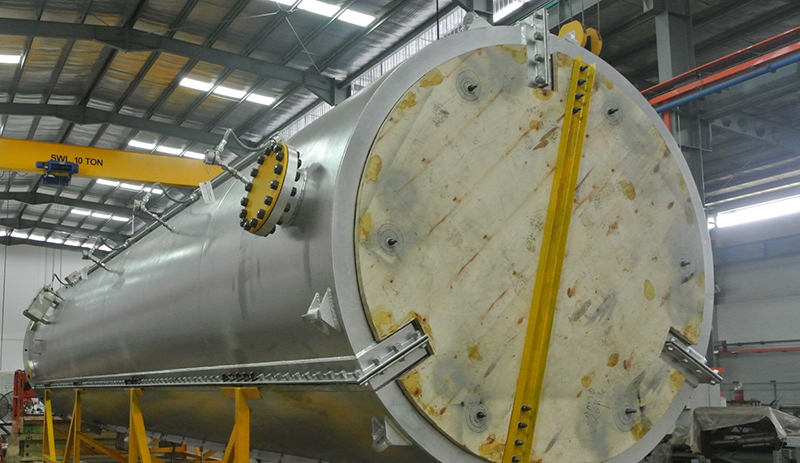
An electric radiant furnace provides indirect process heating to a pressure vessel, reactor, process piping, or coil to heat a process fluid by surrounding a pressure vessel and heating the vessel without penetrating the pressure boundary. A radiant furnace is provided in segments that contain electric resistance heating elements mounted to insulation, and the segments are assembled around a pressure vessel to be heated. When the furnace is energized, the elements generate heat through electric resistance which radiates onto the surrounded pressure vessel to heat the fluid inside. The annular design allows for high temperatures in the region between the furnace and the pressure vessel while the insulation keeps the outside surface of the furnace at temperatures safe for site personnel. ACG can provide either a custom sized radiant furnace to assemble in the field around a vessel provided by others or a furnace pre-assembled with an internal pipe coil or ASME rated pressure vessel that the end user connects to their process piping in the field via flanged connections. Radiant furnaces themselves are not ASME rated pressure vessels, but rather are enclosures supporting insulation and heating elements to heat an internal pressure vessel.
A radiant furnace has the advantage of indirectly heating a process fluid, which means that the electrical heating elements are contained in the furnace itself and not the reactor pressure vessel that the furnace surrounds, so the elements never come into contact with the fluid. This makes the furnace an ideal choice for high temperature corrosive fluid services and two-phase fluid flow that would otherwise damage the heating elements in an immersion heater or exceed the temperature and duty requirements of an impedance heater.
ACG's radiant furnaces are also electrically energized compared to a traditional gas fired furnace, so they offer zero in plant emissions and reduced cost and footprint requirements compared to non-electric furnaces. The electrical heating elements offer precise temperature control with immediate temperature adjustments.
There are no moving parts to the furnace and the thick nichrome heating elements result in little maintenance downtime and a long service life.
A single heater can achieve temperatures up to 2192°F [1200°C] with power duties up to 16 MW at supply voltages up to 690 VAC, and multiple reactors can be modularly added in series for larger duties. A furnace can achieve temperatures required for molten salt storage and pyrolysis applications. This equipment offers high heating capacities at a small footprint.
The furnaces are energized by low voltage 3-phase supply power, with one leg of each phase connected to a resistance heating element circuit. The furnace is typically supplied in three segments with each segment containing a heating element circuit energized by one leg of the 3-phase power. The three furnace segments are assembled around a pressure vessel and bolted together to create 360 degrees of radiant heating focused on the internal vessel.
A radiant furnace can accommodate vessels up to 13.5 ft [4.2 m] in diameter. The furnace enclosure is typically made of carbon steel with internally mounted mineral wool insulation supporting the heating elements. Heating elements can be Nichrome 70-30, Nichrome 80-20, or KAF material depending on the specific duty requirements.
Yes, ACG can design a radiant furnace to include a Z purge on the power junction boxes and the annular space surrounding the heated vessel. In this case, expansion joints must be included in the design, sized either by ACG or by the end user, to create a pressure seal between the furnace and the outside of the heated vessel. Significant differential thermal growth should be expected between the ambient temperature furnace enclosure and the heated pressure vessel located inside.
ACG can include in-house fabricated thermocouples mounted to the furnace enclosure that penetrate the internal insulation to monitor both the air temperature near the heating elements and the pressure vessel skin temperature. We can alternatively supply thermowells on the furnace casing for a customer to install their own thermocouples in the field.
Some pressure vessels have process or instrumentation connections located in the heated area that must protrude through the furnace casing. ACG can incorporate nozzle protrusions in the furnace design and provide expansion joints for field installation connecting the furnace enclosure to the pressure vessel nozzles to ensure a thermal break and weather resistant seal.
Cooling nozzle connections can also be supplied on the furnace enclosure to allow the end user to blow moving air through the heated space and reduce cool down times between furnace operation.
The furnaces typically fail by electrically shorting the resistance heating elements, usually through ambient water intrusion into the furnace's insulation during installation or maintenance. This is not particularly common since ACG designs the furnaces to include a watertight seal on the segment seams and advises end users to ensure that the furnace and insulation is dry before energizing the heating elements. Shorted elements can be inspected or replaced.
Radiant furnaces are typically designed in three 120 degree segments that are assembled around a pressure vessel and bolted together with a gasket along each of the segment seams to create a watertight seal and prevent ambient moisture from intruding into the inside of the furnace. Some end users over-tighten the bolts along the segment seams and warp the segment flanges, which can open leak paths into the furnace.
While we have encountered the above are failure modes, radiant furnaces typically have a 20 to 30 year service life given the robust heating element size and lack of moving parts.
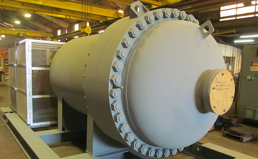
An Impedance Heater is a unique type of electric process heater that offers direct heating of a process fluid without the use of immersed heating elements. A process fluid to be heated is contained in a small diameter pressure vessel resembling a helical coil, and an electrical supply is used to energize the wall of the pressure vessel itself. The electrical resistance of the vessel material causes the wall to heat up and in turn heat the process fluid as it flows through the vessel. Heat is provided directly from the vessel walls which allow higher design temperatures and pressures than immersion heaters that utilize removable electric heater bundles. The coil is contained in an insulated enclosure with all exposed surfaces grounded to ensure protection for site personnel. These are specialized niche pieces of equipment for tough process demands, but we have recently seen an increase in interest as they're electric equipment capable of producing the high temperatures and pressures required while handling process fluids prone to fouling other types of heaters and are contained in a small footprint. This equipment type has a high up front cost but is very efficient with no moving parts or replaceable bundles so offers low maintenance costs.
Low voltage customer supplied 3-Phase power (up to 600 VAC) is run through a step down transformer to create a lower voltage (120 VAC or less) / higher amperage load power that energizes the heater wall to achieve high design temperatures. The transformer is custom designed for the heater duty and is included with the heater, with each leg of the 3-Phase power used to energize sections of the heater wall.
As the electrical resistance of the heater wall material varies with temperature, ACG uses phase angle controlled 3-Leg SCRs to achieve precise control and ensure the heater functions as intended. The heater is electrically grounded inside an enclosure so that there are no electrically energized exposed portions of the heater.
There are no fragile heating elements to short or burn out as the heater's pressure vessel wall itself serves as the heating element. This offers great reliability and low maintenance down time as the heater is essentially wired into supply power, piped to the process fluid, and turned on.
Impedance Heaters are suitable for design duties from 20 kW to 1.5 MW, design temperatures up to 1850°F [1010°C], and design pressures up to 4700 PSIG [325 Bar]. The temperature and pressure combinations are quite high, which allow the heater to be used for supercritical applications.
Typical process fluids are Carbon Dioxide, Ammonia, Supercritical Water, Hydrocarbons, and Tar Products. The heater can accommodate two phase flow and fouling processes that would sideline a typical electric immersion heater, making this a durable piece of equipment for tough process demands.
These can reach temperatures required for some molten salt applications and pyrolysis, which are growing industries in renewable energy storage and plastic recycling respectively.
The materials of construction are selected for both the high design temperature/pressure requirements and electric resistance properties to meet the process duty. The heater vessel shell is typically made from pipe in 321 Stainless Steel, Hastelloy C22 or C276, or Incoloy 800H or 800HT. The heater shell coil is made of small diameter pipe to accommodate high pressure demands and ensure even heating of the process fluid. The coil is housed in a custom enclosure up to 9.5 ft [3 m] Outside Diameter and 12.5 ft [4 m] Overall Height.
Impedance Heaters offer high efficiency and reliable direct heating for tough process duty requirements at high temperature and pressure combinations. They can accommodate two phase process fluid flow and fouling fluid services that would not be suited for an electric immersion heater, and they eliminate fragile heating elements by directly energizing and heating the process vessel wall. They offer precise temperature control and uniform fluid heating and are suitable for emerging industry process requirements.